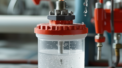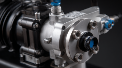
Choosing a Diaphragm Metering Pump in 2026 requires more than comparing flow rates and prices. The right model must match the chemical, pressure, temperature, and dosing accuracy required by your process. A pump handling sodium hypochlorite may need different materials than one dosing a viscous polymer. Small differences matter.
This guide focuses on practical selection decisions drawn from real operating conditions. It examines diaphragm materials, wetted components, flow control, pressure capability, pulse reduction, and maintenance access. It also considers newer expectations, including remote monitoring, energy efficiency, and compatibility with automated control systems. A clear specification sheet helps, but it cannot replace testing under actual process conditions.
Look closely at the details.
A pump rated for 100 liters per hour may perform poorly at very low output. A chemically resistant diaphragm may still fail if pressure, temperature, or installation conditions are misunderstood. Calibration can drift when suction piping is poorly designed. These issues are easy to overlook during procurement. They often appear later as unstable dosing, premature wear, or unexpected downtime.
No selection method is flawless. Manufacturer data may use ideal laboratory conditions, while your plant has fluctuating temperatures and inconsistent fluid properties. That gap deserves attention. Reliable decisions come from comparing verified performance data, service experience, and lifecycle costs. The goal is not simply to buy a powerful pump. It is to choose a dependable Diaphragm Metering Pump that delivers controlled dosing, safe operation, and manageable maintenance over time.
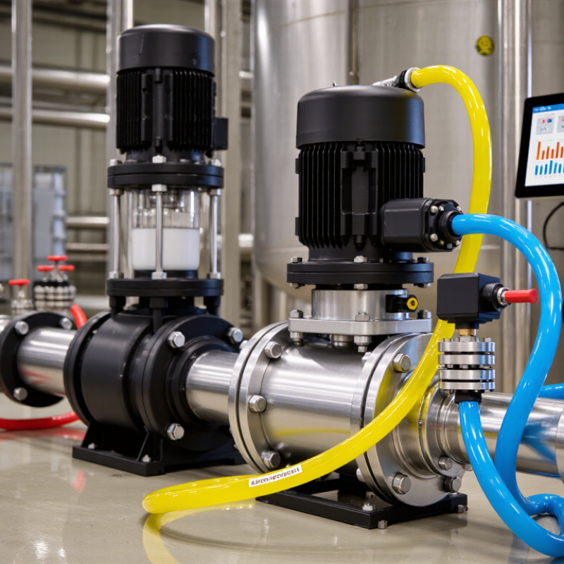
When selecting a diaphragm metering pump in 2026, start by understanding its basic action. A diaphragm metering pump moves measured liquid volumes through a flexible diaphragm. An electric motor or solenoid drives the diaphragm back and forth. During the return stroke, an inlet check valve opens. Liquid enters the chamber. During the forward stroke, the inlet valve closes, while the outlet valve opens. This controlled displacement produces repeatable dosing without placing moving seals directly in the liquid. That matters when the chemical is corrosive, abrasive, or sensitive to contamination. The pump does not “know” the dose automatically. Calibration still depends on pressure, temperature, viscosity, and stroke settings.
In practical selection, match the required flow rate and discharge pressure before comparing features. Check wetted materials carefully. A useful specification sheet should identify diaphragm, valve, and head materials. Pulsation may also affect injection points, so a dampener or suitable control strategy can be necessary. Modern units may provide flow feedback, leak detection, and remote status data. These features improve traceability, but they cannot repair poor installation. From field experience, undersizing is less common than ignoring back pressure. My early calculations also relied too heavily on catalog capacity. Real fluids behaved differently. Test the actual liquid when possible, then confirm capacity across the expected operating range. Keep spare diaphragms and inspect valves during scheduled maintenance.
How to Choose a Diaphragm Metering Pump in 2026?
Before choosing a diaphragm metering pump, define the process, not just the target flow. Record minimum, normal, and maximum flow rates. Include discharge pressure, suction conditions, fluid temperature, viscosity, density, and vapor pressure. Chemical concentration matters too. A pump handling thin water behaves differently with a viscous slurry. Specify solids size and percentage. Small particles can change diaphragm life and valve performance.
The U.S. Department of Energy reports that pumping systems may consume 25–50% of industrial electricity. This figure covers complete systems, not only metering pumps, but it shows why operating conditions deserve careful review. Ask for required turndown, dosing accuracy, pulse tolerance, and daily operating hours. Then check diaphragm material, valve materials, and seal compatibility against the actual chemical data sheet. Do not rely on fluid names alone. “Acid” is not a complete specification.
Tips: Test the real fluid when possible. Measure pressure at the pump inlet and outlet. Confirm whether the pump must run dry, restart frequently, or handle backpressure changes. A calibration column can reveal errors that a catalogue curve hides. Digital monitoring is useful, but sensors still need maintenance. The International Organization for Standardization emphasizes performance verification and operating documentation in pump-related standards. Selection remains partly imperfect. Field conditions often change after commissioning. Leave adjustable capacity, protective interlocks, and accessible inspection points where practical.
Start by defining the required flow rate, maximum discharge pressure, fluid properties, temperature, solids content, control method, and operating cycle. The chart below converts common pressure requirements into equivalent water head values. At approximately 4°C, 1 bar equals 100 kPa and about 10.197 meters of water head.
How to use this chart: Select a pump that can deliver the required flow at the actual maximum discharge pressure, not only at the normal operating point. For fluids with a different density, the equivalent head will change, so confirm the process fluid’s specific gravity before final sizing.
How to Choose a Diaphragm Metering Pump in 2026?
How Do You Match Pump Capacity, Pressure, and Materials?
Choosing a diaphragm metering pump starts with the real dosing point, not the catalog maximum. Record the required flow range, discharge pressure, fluid temperature, and suction conditions. A pump rated for 100 L/h may perform poorly at 5 L/h without suitable turndown control. Leave practical margin, but avoid excessive oversizing. Large pumps can create unstable low-flow adjustment.
Pressure must include line loss, injection-point resistance, elevation, and valve backpressure. Measure the system while operating, if possible. Do not rely only on an empty-pipe calculation. The pump’s rated pressure should exceed the working pressure with a sensible allowance. Excessive margin, however, may increase energy use and stress the diaphragm. Calibration at the actual operating pressure is more trustworthy than a factory chart alone.
Material selection follows the chemical, temperature, concentration, and cleaning method. Wetted parts may require compatible plastics, alloys, elastomers, or ceramic components. Check permeability and swelling, not just corrosion resistance. A material that survives briefly may fail after months of cycling. Small details matter. Diaphragm compatibility is often overlooked. Field teams sometimes specify the right head material but the wrong seal compound. That mistake is easy to miss. Review chemical data, maintenance records, and current safety requirements with a qualified engineer before purchase.
| Chemical / Service | Typical Concentration | Design Flow Range | Required Discharge Pressure | Recommended Wetted Materials | Diaphragm / Seal Material | Capacity-Matching Guidance | Important Selection Check |
|---|---|---|---|---|---|---|---|
| Sodium hypochlorite dosing | 5–12% NaOCl | 0.5–60 L/h | 2–6 bar | PVC, PE, or PVDF; PTFE valve components | PTFE diaphragm; EPDM or PTFE seals subject to compatibility review | Select a rated capacity about 10–20% above the maximum calculated dose to allow calibration and operating margin. | Avoid copper, brass, and other materials that may accelerate decomposition or corrosion; provide gas-release management where required. |
| Ferric chloride dosing | 10–40% FeCl₃ | 1–100 L/h | 3–8 bar | PVC, CPVC, PVDF, or PTFE-lined wetted parts | PTFE diaphragm; EPDM or FKM seals after chemical confirmation | Check the actual maximum viscosity and density; concentrated ferric chloride can require increased suction allowance. | Consider corrosion allowance, flush connections, and a corrosion-resistant injection fitting. |
| Sulfuric acid dosing | 5–50% H₂SO₄ | 0.2–50 L/h | 2–7 bar | PVDF, PTFE, or suitable fluoropolymer-lined components | PTFE diaphragm and PTFE-based seals where compatible | Use the maximum required flow at the actual backpressure, not the pump’s zero-pressure capacity. | Material compatibility changes with concentration and temperature; verify chemical-resistance data before final selection. |
| Caustic soda dosing | 10–50% NaOH | 1–80 L/h | 2–6 bar | PP, PVC, PVDF, or PTFE | PTFE diaphragm; EPDM is often considered, subject to concentration and temperature | Allow for the higher density of concentrated solution when sizing the drive and checking hydraulic performance. | Confirm maximum liquid temperature and seal compatibility; concentrated caustic can stress some plastics and elastomers. |
| Alum or polymer solution | 0.1–10% | 2–150 L/h | 2–5 bar | PVC, PP, PVDF, or 316 stainless steel depending on chemistry | PTFE diaphragm; EPDM or FKM seals after compatibility review | Use a slower stroke rate or larger displacement when shear-sensitive polymer solutions are being dosed. | Check viscosity, flocculation risk, and whether a pulsation dampener is needed for stable downstream mixing. |
| Biocide or corrosion inhibitor | Ready-to-use or diluted solution | 0.1–30 L/h | 2–8 bar | PVDF, PTFE, PVC, or 316 stainless steel according to SDS data | PTFE diaphragm; seal material must be selected from the chemical SDS and compatibility chart | For low-flow control, prioritize accurate stroke adjustment, minimum stable flow, and calibration repeatability. | Check whether the formulation contains solvents, surfactants, or oxidizers that may attack elastomers. |
| Abrasive slurry or lime suspension | 1–20% suspended solids | 5–200 L/h | 2–5 bar | Abrasion-resistant plastics, ceramic valve seats, or suitable alloy components | PTFE or reinforced diaphragm; elastomer selection depends on pH and solids | Use conservative valve velocities and confirm that the pump can pass the largest particle size without clogging. | Provide agitation, flushing, and accessible check valves; abrasive service can reduce valve and diaphragm life. |
Engineering note: The ranges above are representative application values for preliminary selection. Final sizing should be verified against the chemical safety data sheet, temperature, viscosity, suction conditions, required accuracy, and the selected pump’s certified performance curve.
Choosing a diaphragm metering pump in 2026 starts with the fluid, not the catalog page. Measure viscosity, temperature, solids, vapor pressure, and required flow range. A mechanical diaphragm suits many steady-duty applications. A hydraulically actuated diaphragm offers stronger protection against overload and better accuracy at higher pressures. For abrasive or crystallizing fluids, diaphragm material and head geometry may matter more than maximum capacity. Fit matters.
Drive type changes how the pump behaves. Motor-driven units provide controlled, repeatable dosing and suit continuous plant operation. Solenoid-driven pumps are compact and responsive, especially at lower flow rates. Pneumatic drives can work in hazardous or wet areas, but they need clean, stable air. Check the real operating point, not only the advertised maximum. A pump rated for 100 liters per hour may lose accuracy near 10 liters per hour.
Controls should match your process skill and maintenance habits. Manual stroke adjustment is simple, but it can drift after pressure changes. A variable-frequency drive can coordinate speed with production flow. Remote signals, pulse inputs, flow verification, and low-level alarms add useful protection. Do not add every feature automatically. More wiring creates more failure points. I have seen excellent pumps perform poorly because calibration was skipped after installation. Leave room for a calibration column, accessible valves, and safe diaphragm inspection. The best choice may be slightly oversized, but excessive oversizing can reduce control quality.
Choosing a diaphragm metering pump in 2026 requires more than comparing flow rates. Safety begins with chemical compatibility, pressure control, and leak prevention. Check the diaphragm material against the liquid, temperature, and concentration. Confirm that the pump includes overload protection and a suitable relief path. A transparent leak chamber can reveal failure before liquid reaches nearby equipment. Small details matter.
Maintenance should be measured in access time, not only service intervals. Inspect how easily operators can replace the diaphragm, valves, and seals. A pump requiring special tools may increase downtime during a night shift. Ask for clear maintenance instructions, inspection records, and realistic spare-part availability. Calibration should also be simple. A graduated cylinder and timed test can expose inaccurate dosing. Do not trust the display alone.
Cost comparisons must include electricity, consumables, labor, and unplanned shutdowns. A cheaper pump may become expensive after repeated diaphragm failures. Review the expected cycle life under your actual pressure, not laboratory conditions. Long-term reliability depends on stable control, strong construction, and documented testing. Request performance data at minimum and maximum capacity. Field feedback is valuable, but it can be incomplete. A spreadsheet can still mislead. Leave room for uncertainty, and verify critical claims with operating trials.