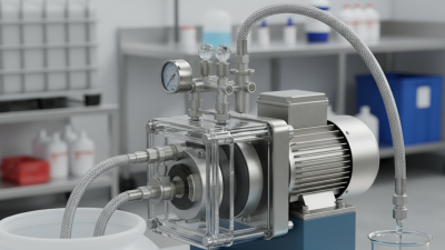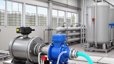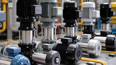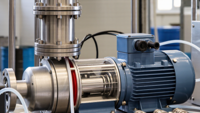
Choosing the 2026 Best Diaphragm Dosing Pump for Industrial Applications starts with the process, not the brochure. What chemical must be metered? At what flow, pressure, and temperature? A pump that performs steadily in a clean-water test may behave differently with viscous fluids, abrasive particles, or frequent start-stop cycles. Small details matter.
The International Energy Agency’s Energy Efficiency 2023 report found that global energy-intensity improvement slowed to 1.3% in 2022, below the recent historical average. That is a broad industrial signal, not a pump-specific performance benchmark. Still, it supports closer attention to operating efficiency and maintenance. IEA Executive Director Fatih Birol has described energy efficiency as “the first fuel.” For dosing systems, that idea begins with matching the pump to the duty and checking actual consumption, accuracy, and service requirements.
Standards matter, too. API 675 covers controlled-volume positive-displacement pumps, a useful reference when evaluating metering performance and design expectations. But compliance alone cannot guarantee a good fit. Review chemical compatibility, turndown, pulsation control, diaphragm monitoring, spare-part access, and the supplier’s documented test conditions. Ask for evidence.
This guide compares diaphragm dosing pump options for practical industrial duties, from water treatment to chemical processing. It focuses on measurable specifications and service realities. No single model suits every plant. That is worth remembering.
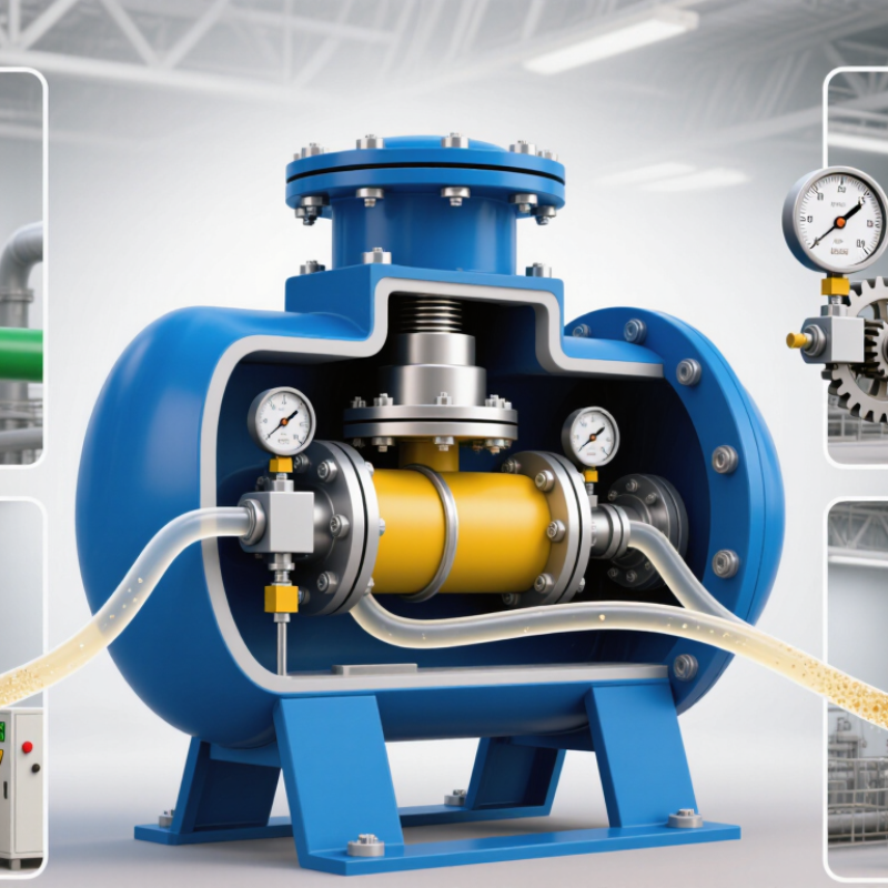
A diaphragm dosing pump moves a measured volume of liquid using a flexible membrane. A motor, solenoid, or other drive mechanism moves the diaphragm inside a pump head. As the diaphragm retracts, pressure falls and an inlet check valve opens, drawing liquid into the chamber. When it moves forward, the inlet closes and the outlet valve opens, pushing liquid into the process line.
Small stroke, steady feed.
This positive-displacement action suits controlled chemical dosing in water treatment and industrial processes. The USGS report Estimated Use of Water in the United States in 2015 puts public-supply withdrawals at about 39 billion gallons per day. That scale makes reliable treatment processes important, though the figure is not a measure of pump use.
Actual dosing accuracy depends on the installation, not just the pump. Check chemical compatibility, discharge pressure, and whether gas bubbles can collect in the liquid.
Operators can often adjust stroke length or frequency to change the feed rate. But settings need verification: measure the delivered volume under real operating conditions, especially after changing pressure or fluid viscosity. A calibration cylinder, clear tubing, and a stable back-pressure valve make checks easier to interpret.
It sounds simple. It is not always. Valve wear, trapped air, or a partially blocked line can cause the delivered dose to differ from the setting, so maintenance records matter.
A diaphragm dosing pump turns controlled motion into a measured flow. Its drive moves a diaphragm inside the pump head, while inlet and discharge check valves guide the liquid in one direction. Stroke length and speed set the theoretical dose, but actual delivery also depends on liquid viscosity, suction conditions, and valve condition. Small details matter.
The metering cycle begins as the diaphragm retracts. The chamber expands, pressure falls, and the inlet valve opens to draw liquid in. The discharge valve stays closed. Then the diaphragm advances, chamber pressure rises, the inlet valve closes, and the discharge valve opens. A measured volume leaves the head. The rhythm repeats.
Watch the valves closely. A particle on a valve seat can cause backflow and uneven dosing. Trapped air may compress instead of moving liquid, so venting and priming are important. On a real installation, verify output by collecting and measuring flow under operating conditions. A nameplate value is only a starting point. Calibration can still drift as parts wear, and that is easy to overlook.
| Component or Cycle Stage | What Happens | Key Components | Industrial Selection and Operating Notes |
|---|---|---|---|
| Key Pump Components | |||
| Drive and speed control | Provides the reciprocating motion that moves the diaphragm. A variable-speed drive can adjust the number of dosing cycles per minute. | Electric motor, gearbox or drive mechanism, speed controller | Confirm supply voltage, control signal, duty cycle, and required turndown. Flow is commonly adjusted by changing stroke speed, stroke length, or both, depending on pump design. |
| Diaphragm and liquid end | The diaphragm separates the process liquid from the drive mechanism and changes the volume of the pump chamber. | Diaphragm, pump head, seals, liquid-end connections | Select wetted materials for chemical compatibility, temperature, and pressure. PTFE-faced diaphragms and corrosion-resistant head materials are used in suitable applications, but compatibility must be checked against the specific fluid. |
| Suction and discharge check valves | Open and close in response to pressure differences to direct liquid through the pump in one direction. | Valve bodies, seats, balls or other closure elements | Valve design and materials should suit the liquid’s viscosity, solids content, and chemical properties. Proper sizing and installation help reduce leakage, loss of prime, and inconsistent dosing. |
| Stroke adjustment and calibration | Sets the displacement or operating rate used to control the delivered flow. | Stroke-length adjuster, speed setting, calibration column or measured collection vessel | Verify actual output at the operating pressure and with the process liquid, where practical. A basic theoretical relationship is: flow ≈ displacement per stroke × strokes per unit time; actual output can vary with pressure, valve condition, and fluid properties. |
| Pressure protection and injection accessories | Protects the system and supports stable delivery into the process line. | Pressure-relief valve, back-pressure valve, pulsation dampener, injection valve, pressure gauge | Use pressure-protection devices appropriate to the system design. A back-pressure valve can help maintain stable check-valve operation when line pressure is low or variable; a relief valve must discharge to a safe, suitable location. |
| The Metering Cycle | |||
| 1. Suction stroke | The drive retracts the diaphragm, increasing the pump-chamber volume and reducing its pressure. The suction check valve opens as liquid enters the chamber. | Drive mechanism, diaphragm, pump chamber, suction check valve | Keep the suction line appropriately sized and free of air leaks. Excessive suction lift, clogged strainers, or high liquid viscosity can reduce filling and cause under-delivery. |
| 2. Suction-to-discharge transition | The diaphragm changes direction. The suction valve closes as chamber pressure begins to rise. | Diaphragm, suction and discharge check valves | Check valves need time and suitable differential pressure to seat correctly. Entrained gas or debris can interfere with valve closure and reduce metering consistency. |
| 3. Discharge stroke | The drive advances the diaphragm, reducing chamber volume. The discharge check valve opens when chamber pressure exceeds discharge-line pressure, sending liquid into the process line. | Drive mechanism, diaphragm, pump chamber, discharge check valve | The pump must be selected for the required flow and discharge pressure. Actual capacity depends on pump configuration, operating conditions, fluid properties, and system accessories. |
| 4. Discharge-to-suction transition | The diaphragm reverses direction, chamber pressure falls, and the discharge check valve closes before the next suction stroke begins. | Diaphragm, discharge check valve, drive mechanism | Inspect for leakage, abnormal vibration, and changes in delivered flow. Follow the pump manufacturer’s maintenance instructions for diaphragm and valve inspection intervals. |
| Selection note: There is no single diaphragm dosing pump that is best for every industrial duty. Match the pump to the required flow, discharge pressure, chemical compatibility, temperature, control method, and installation conditions. The information above is general engineering guidance, not a product-specific performance specification. | |||
Industrial dosing is rarely just a flow-rate problem. A pump must deliver a repeatable volume against changing pressure while handling the actual fluid and operating schedule. In a water-treatment skid, demand may stay steady in the morning, then drop as the system cycles. Small details matter. Record normal and peak flow, discharge pressure, fluid temperature, and required turndown before comparing pump capacities.
Diaphragm material, pump-head material, and seals need to suit the chemical and temperature. Compatibility charts are useful, but operating conditions can change the result; confirm selections with qualified technical support. Viscosity, entrained gas, and suspended particles can also affect suction and dosing consistency. Controls should fit the process: a basic local setting may be enough, while remote adjustment may be needed when flow follows a changing signal. Check whether pulsation control and pressure protection are required for the installed line.
At commissioning, verify delivery under operating pressure with a calibrated measurement method, not only during free discharge. Record the settings and conditions. A sensor can improve monitoring, but it also adds maintenance. Not every process agrees. If operators cannot inspect or service the pump safely, a precise specification is not enough. Review the assumptions after startup; field conditions often reveal a variable that the initial selection missed.
For 2026, choose a diaphragm dosing pump by defining the actual duty, not just the maximum flow on a specification sheet. Record normal and peak flow, discharge pressure, turndown, fluid temperature, viscosity, and any suspended solids. A pump rated for the right flow may still struggle against real piping losses.
Check wetted-material compatibility, diaphragm life, pulsation, and how the pump responds to changing backpressure. The U.S. Department of Energy’s Improving Pumping System Performance: A Sourcebook for Industry reports that pumping systems use nearly 20% of global electricity and can account for 25–50% of energy use in some industrial facilities. These are system-level figures, not dosing-pump efficiency estimates. Still, they make it worth assessing the pump, drive, and piping together.
Ask suppliers for documented accuracy and repeatability at your operating pressure, not only at test conditions. Confirm calibration procedures, leak detection, spare-part access, and maintenance intervals. Test the actual process fluid where possible; water trials may not reveal behavior with viscous or crystallizing liquids. Small details matter. I would also revisit the specified turndown after commissioning, since a theoretically suitable range can prove awkward in day-to-day operation.
A diaphragm dosing pump performs best when its capacity matches the process, not just the nameplate rating. Confirm the required flow at actual discharge pressure, fluid temperature, and viscosity. A pump that handles water well may deliver differently with a thicker chemical. Watch for uneven flow. Pulsation can affect sensitive injection points, so check whether a dampener is needed. During commissioning, compare measured output with the set rate; small deviations matter in continuous dosing.
Safety begins with compatible wetted materials and a correctly rated pressure-relief path. Never isolate a running pump from its relief route. Use containment beneath connections, and inspect tubing for swelling, cracks, or residue. Chemical splash protection should suit the fluid and the task. A common commissioning surprise is trapped air: it can interrupt dosing while the pump appears to be running normally. Still, site conditions vary.
Maintenance should follow the fluid, duty cycle, and manufacturer’s service guidance. Inspect the diaphragm for wear, and check valves for deposits or sticking. Replace seals when inspection or performance indicates a need, not simply because they look old. Record calibration results, leaks, and service dates. Keep spare diaphragms and valve components available where downtime is costly. Check again after startup. A neat log helps, though it cannot replace a careful inspection.