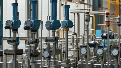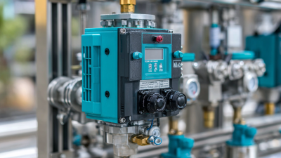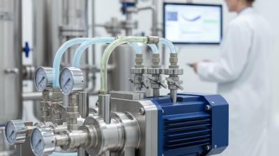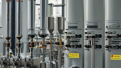
An Industrial Dosing Pump delivers controlled amounts of liquid into a manufacturing or treatment process. Unlike a general transfer pump, it focuses on accuracy, repeatability, and chemical compatibility. Operators commonly use these pumps for acids, polymers, disinfectants, nutrients, and corrosion-control solutions. The details matter.
A typical system includes a pump head, diaphragm or plunger, motor, control unit, valves, and calibration equipment. Its performance depends on pressure, viscosity, temperature, and suction conditions. Experienced technicians check these factors before selecting a model. They also review manufacturer flow curves and material specifications. A pump rated for clean water may fail quickly with abrasive or highly corrosive chemicals. That sounds simple. It is not always simple.
This guide explains how an Industrial Dosing Pump works, where it fits, and how professionals evaluate its performance. Practical experience shows that accurate dosing requires more than adjusting a stroke length. Calibration, pulsation control, leak prevention, and routine inspection all affect process reliability. Operators should record actual output, not trust the display alone. Small errors can change product quality or treatment results. No pump is perfect. Even well-designed equipment can drift when seals wear or operating conditions change. Therefore, sound selection combines engineering data, site experience, and applicable safety requirements. This approach supports dependable operation without promising unrealistic precision.
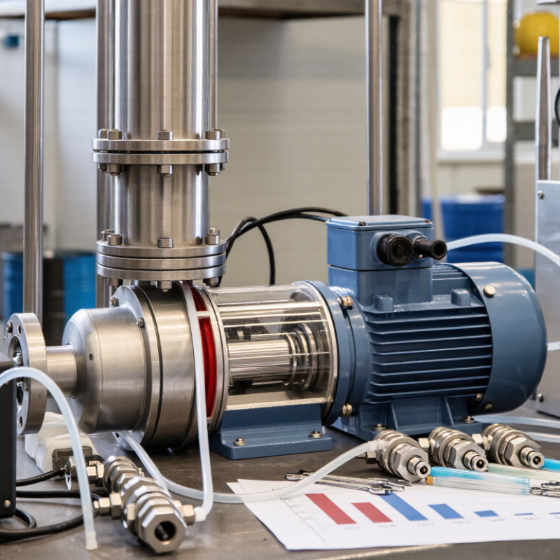
Industrial dosing pumps deliver controlled chemical volumes into water, process, and manufacturing systems. Their defining feature is precision metering, often targeted within ±1% accuracy under stable operating conditions. That figure describes delivered volume, not a guarantee for every installation. Temperature, viscosity, pressure, and trapped air can change performance.
A practical system uses a calibrated pump, accurate flow measurement, and regular verification. A 100-liter batch should receive approximately 99 to 101 liters when ±1% accuracy is achieved. Small errors still matter. Overfeeding can waste chemicals, while underfeeding may reduce treatment effectiveness. API 675, the controlled-volume pump standard, emphasizes repeatable performance, pressure control, and safe design practices.
Market data also shows why precision matters. Fortune Business Insights estimated the global dosing pump market at about 7.57 billion dollars in 2023. It projected growth to approximately 10.79 billion dollars by 2032. MarketsandMarkets reported a different forecast, showing the value of independent comparison. Forecasts vary. Site testing remains more reliable than sales projections. Engineers should record stroke length, pulse frequency, suction conditions, and actual discharge volume. Calibration can expose an uncomfortable truth: a pump may meet ±1% in a laboratory, but not on a poorly maintained process line.
What Is an Industrial Dosing Pump?
Core Components: Pump Head, Diaphragm, Valves, and Drive System
An industrial dosing pump delivers controlled liquid volumes into a process line. It may handle treatment chemicals, additives, or conditioning agents. Accurate dosing protects product quality and keeps process conditions stable. However, accuracy depends on installation, calibration, and fluid properties.
The pump head forms the chamber where liquid enters and leaves. Inside it, the diaphragm moves back and forth, creating suction and discharge strokes. A chemical-resistant diaphragm should match the fluid’s temperature and concentration. If it hardens, stretches, or develops a small tear, flow accuracy can change quickly. Small details matter.
Inlet and outlet valves control one-way movement through the head. Blocked, worn, or poorly seated valves can cause weak output and unstable pressure. The drive system controls diaphragm speed and stroke length. Manual, electric, or electronically controlled drives may be used, depending on process requirements. During field checks, technicians often compare the expected volume with a timed collection sample. This simple test can reveal errors that display settings hide. Sizing is not always perfect on the first attempt, especially when viscosity changes with temperature. Careful observation and repeated calibration remain necessary.
An industrial dosing pump delivers measured chemical volumes into water, process fluids, or production lines. Its output is commonly specified from millilitres per hour to cubic metres per hour. For example, 250 mL/h equals 0.00025 m³/h. That conversion looks simple, but concentration, viscosity, temperature, and back pressure can change the real result.
Stroke control determines how much liquid moves during each diaphragm or piston cycle. Stroke length changes the volume per cycle, while stroke frequency changes cycles per minute. A controller may reduce both settings to achieve a low feed rate, then increase frequency when demand rises. Flow should be confirmed by calibration, not assumed from the dial. According to the U.S. Department of Energy’s Pumping System Assessment Tool guidance, pumping systems can consume 25% to 50% of industrial facility electricity in some applications. Accurate dosing cannot fix an inefficient process, but stable control can reduce overfeeding and unnecessary recirculation.
A practical test uses a graduated cylinder, timed collection, and several operating points. At 100 mL/h, collecting liquid for six minutes should produce about 10 mL. Small errors become significant at low rates. The European Commission’s Best Available Techniques documents for waste treatment emphasize controlled chemical use and monitored operating conditions. Still, published performance data often assumes clean fluid and steady pressure. That assumption can fail. Crystallization, trapped air, or worn check valves may reduce actual flow. I would record suction pressure, discharge pressure, fluid temperature, and calibration results beside every setpoint.
What Is an Industrial Dosing Pump?
Industrial dosing pumps deliver measured volumes of liquid chemicals into water, process lines, or reactors. Their value depends on repeatable flow, pressure stability, and material compatibility. The U.S. Department of Energy reports that pumping systems may consume 25% to 50% of industrial facility electricity. Efficient dosing therefore requires correct sizing, not simply a powerful motor.
Diaphragm pumps use a flexible membrane and suit corrosive chemicals, wastewater, and variable pressures. They isolate the fluid from moving parts, reducing leakage risks. Plunger pumps provide higher pressure and precise metering. However, their seals need careful inspection. Peristaltic pumps compress a flexible tube, making them useful for abrasive slurries or fluids requiring clean handling. Tube wear can quietly reduce accuracy. It happens.
Progressive cavity pumps move fluid through a rotating rotor and stator. They handle viscous liquids, polymers, and fluids containing suspended solids. Their steady flow is helpful, but dry running can cause rapid damage. A 2023 report from the International Energy Agency highlights the continuing importance of industrial efficiency and equipment optimization in reducing energy demand. Yet energy figures alone cannot select a pump. Operators should compare viscosity, pulsation, pressure, maintenance access, and chemical temperature. Accuracy comes first. In practice, the cheapest design may create higher costs through calibration drift, tube replacement, or unplanned shutdowns. No pump wins every test.
Industrial dosing pumps deliver controlled amounts of liquid chemicals or process fluids. The most common designs differ in flow range, pressure capability, fluid compatibility, and shear sensitivity.
Chart guide: The logarithmic scale shows indicative flow ranges commonly encountered in industrial metering applications. Actual performance depends on pump size, pressure, viscosity, temperature, and fluid properties.
An industrial dosing pump meters a controlled volume of liquid into a process. It supports water treatment, chemical processing, and energy applications. Unlike a transfer pump, it prioritizes accuracy over high flow. Some systems operate at pressures approaching 400 bar. That is demanding.
Selection should begin with actual discharge pressure, flow rate, temperature, and fluid behavior. The rated pressure must exceed normal operating pressure, including startup surges. A small safety margin matters. However, pressure alone cannot define the right pump. Viscosity, pulsation, suction conditions, and required turndown also influence performance. A practical mistake is selecting from maximum pressure only. That approach can create poor control at low flow.
Materials require equal attention. Wetted parts must resist corrosion, erosion, and chemical swelling. Stainless steel may suit many services, but it is not universally safe. Strong oxidizers, acids, solvents, and abrasive slurries can demand different alloys, ceramics, diaphragms, or seal materials. Temperature changes can alter clearances and seal behavior. A compatibility chart helps, but field conditions may differ from laboratory data. Verify the fluid concentration and impurities.
API 675 provides a recognized framework for controlled-volume positive displacement pumps. Its requirements support repeatable capacity, mechanical integrity, testing, and documentation. A reliable specification should identify pressure, materials, accuracy, calibration conditions, and inspection records. Engineers should review pulsation dampening and relief protection as part of the package. The first calculation is rarely perfect. Actual commissioning data may expose assumptions that need correction. That is normal engineering practice.